The Windows calculator emulators, hp29w and hp67w, come with the same advanced features as the HTML5 microcode versions did. They just work a little differently and there are some additional features.
Getting Starting
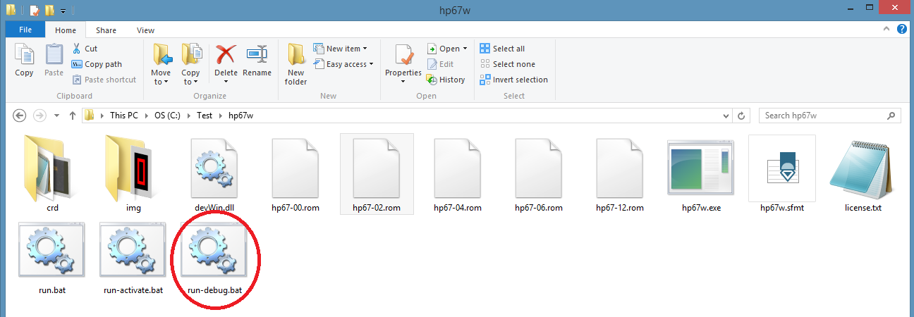
Starting the debugger is pretty easy. Instead of double-clicking the run.bat icon, just double-click the run-debug.bat icon:
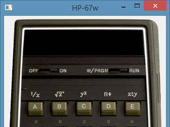
You end up with an “on but blank” calculator; like
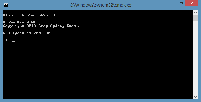
And a second window like:
Getting out
Now there are a number of things you can do at the ">>> " prompt. One of the important ones is entering "q" (press q then the Enter key). That gets you out again.
If you got into the debugger by mistake and don’t remember, or haven’t read, these instructions; you can always click the [X] buttons at the top right of the two windows.
More useful commands
If you enter a "?" at the ">>> " prompt, you’ll get a list of commands. These are:
>>> ?
dr                        Display Registers
ddN                       Display Data register bank N (0-3,9)
dp                        Display Program counter and step
di                        Display cpu Internals
srNAME val                Set Register NAME to value
sdNN val                  Set Data register NN(10) to value(14BCD)
sp addr val               Set Program address(oct) to value(oct)
st num                    Set Talk (1=GEN 2=MEM 4=CRD)
l[o][h] [address]         List program [with opcodes in octal and/or hex]
g [address][,brk]*        Go (run program) [starting at address][with breakpoint
(s)]
t[b][s] [count]           Trace program [in Brief or Smart mode]
return                    single step program
q                         Quit
>>>
Let’s walk through these.
Display registers
>>> dr
A=00000000000000 D=00000000000000 M1=00000000000000 P= 0
B=00000000000000 E=00000000000000 M2=00000000000000
C=00000000000000 F=00000000000000 S =................
>>>
The main registers inside the microcode CPU are the A-F registers, the M1 and M2 registers, the S register and the P register. Many of these were present in earlier generation calculators. There was an M register which has now become two, the M1 and M2 registers. The S register was 12 bits long but it is now 16 bits.
A-F, M1 and M2 all hold 14 binary coded decimal values. You can see 14 digits displayed above for each of them.
For most of the calculator’s time, it will have ordinary numbers stored in the registers. These are values that it will add, subtract, multiply, divide, square root, etc. Ordinary numbers appear in the registers as:
smmmmmmmmmmexx
where "s" is the sign of the number ("0" for positive, "9" for negative), "m" is the mantissa (explained shortly), "e" is the exponent sign and "x" is the exponent.
Any number can be put into scientific notation. For example:
   5 =  5   x 10^0
  23 =  2.3 x 10^1
  .7 =  7   x 10^-1
-200 = -2   x 10^2
Internally, the calculator uses scientific notation for every number operation. So, the "23" example above appears in the registers as:
02300000000001
Like the prior calculator models, the A and B registers are connected to the display. "A" can be considered the value and "B" as the format. This statement isn’t always true – both registers are also used for calculating things before it figures out what to display. This is why we see a flickering display at times.
On most calculators, what users know as the X, Y, Z and T registers are the CPU C, D, E and F registers above. It might be a little different for the HP-29C which needs to retain information when the power is off.
P is a pointer. It goes from 0-13 and points into part of a register i.e. at one of the 14 digits.
S is a set of flags. These are used to remember conditions (like "the ‘f’ key was pressed") but some are also connected to hardware (eg the W/PRGM-RUN switch or the low battery sensor).
Display data
>>> dd0
data[ 0]=00000000000000
data[ 1]=00000000000000
data[ 2]=00000000000000
data[ 3]=00000000000000
data[ 4]=00000000000000
data[ 5]=00000000000000
data[ 6]=00000000000000
data[ 7]=00000000000000
data[ 8]=00000000000000
data[ 9]=00000000000000
data[10]=00000000000000
data[11]=00000000000000
data[12]=00000000000000
data[13]=00000000000000
data[14]=00000000000000
data[15]=00000000000000
>>>
Both calculators have RAM chips for program and data storage. There are 16 memories in a RAM chip and each contains 14 BCD digits. Each digit is 4 bits so, in modern terms, there are 112 bytes in a RAM chip.
You can use "dd" and a number to see what’s in the RAM chips. 0 shows you registers 0-15, 1 16-31, and so on.
There will always be a pattern that relates STO/RCL memory numbers to data storage register numbers, and it is often simple, but it was the designer’s choice of how the two numbers relate. Don’t just assume (i) register 18 will be in RAM chip 1 ie data register 18. It might be or might not.
With the HP-67, the card reader circuit includes two data registers used for transferring bits to a card and from a card. These show up, in the HP-67, as if they were RAM chip 9. You can view these during or after a card read / write operation. (You can also view them at other times but they’re pretty boring – zeros – if they haven’t been used).
Display program
>>> dp
00000: nop
As you can see, this is pretty simple. It just shows the current program counter value and program step. This is what will get run if you single-step or run the microcode program.
Display internal
>>> di
Display          : on (12 digits)
Arithmetic base  : 10
Ram address      : 0
f                : 0
bank/dlyrom      : 0/-1
sp, stack        : 0 [00000,00000]
lastkey          : 00
CRC R            : ............
>>>
The Woodstock CPU has some internal state information. You can peer inside the chip using this command and see how things change. For the HP-67, you can also see the Card Reader Circuit (CRC) R flags. These note things like card inserted, motor on, etc.
You may already know that the HP-67 uses the older style 15 digit display and the HP-29C uses the newer 12 digit version. There is an instruction that switches the processor from dealing with a 12 digit display to one with 15 digits. At power up, the Woodstock CPU is in 12 digit mode (as shown in the example above).
Set register
>>> sra fbcc1fffffffff
You can set a register by giving its name and a value. The example above sets register A to FBCC1FFFFFFFFF.
At startup, with zeros in register B, this displays on a HP-67 as:
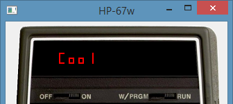
Whilst you use BCD digits (or hex ones) for A-F, M1 and M2; you use a decimal number for P and a "dot pattern" for S. The key is to enter it like it displays.
"srs ..2.4…..a….." will set s2, s4 and s10 and clear the others.
You can also use "srpc (value)" to set the program counter to (value). The program counter is normally displayed in octal so you set it with an octal value.
Set data
>>> sd25 02460000000000
>>> dd1
data[16]=00000000000000
data[17]=00000000000000
data[18]=00000000000000
data[19]=00000000000000
data[20]=00000000000000
data[21]=00000000000000
data[22]=00000000000000
data[23]=00000000000000
data[24]=00000000000000
data[25]=02460000000000
data[26]=00000000000000
data[27]=00000000000000
data[28]=00000000000000
data[29]=00000000000000
data[30]=00000000000000
data[31]=00000000000000
>>>
The above example sets the content of data register 25 to +2.46 x 10^+00, ie 2.46 in normal display form (FIX2).
On a HP-67, data register 25 doesn’t map to what we’d normally think of as memory 25 (the I memory – h ST I, h RC I). This RAM chip is actually used for storage of user programs. If you run the calculator (see later), switch to W/PRGM and single step (SST) or GTO . 1 6 0, you’ll see some user program steps have appeared.
Hex code 46 is "h X<->I" and 02 is "g x^2". You’ll see those instructions at step 160 and 161. Seven program steps, each with two hex digits, fit in a 14 digit data storage register. The same applies for both the HP-67 and the HP-29C but the mapping between data storage registers and program steps will be different, if only because each supports a different number of program steps.
Note that "dd" displays a set of 16 registers so you use 0, 1, 2 or 3 to work through 64 registers; but "sd" sets a single register – so you need to use 0, 1, 2, …, 63 to work through 64 registers. It is more convenient to have "dd" show 16 at a time and more sensible to be able to set a single register instead of having to enter 16 values in one command.
Set program
>>> sp 0 123
>>>
If you want or need to patch a microcode program, or if you want to add some steps in unused parts of one of the ROMs; you can use "sp address value". Both address and value are in octal. It’s a bit cumbersome when compared to an "assemble" command, but it is there if you need it.
None of the ROMs on disk are modified so you can try things out and recover if you get something seriously wrong. You just restart the simulator to load the original microcode again. If you do want to commit changes, I’d suggest saving the original ROM files and then patching them. Each ROM file consists of 1024 x 2 byte words in sequence. The most significant bits are stored first and then the least significant ones (big-endian format). Note that, despite the available 16 bits in each word, the Woodstock processor only uses the bottom 10 bits as the opcode.
Set talk
>>> st 7
>>>
Normally, you’d only see the microinstructions and, in most cases the registers, when tracing a microcode program. Set talk turns on some additional displays during some instructions. This works when tracing, or when running.
A value of 1 turns on information about some general instructions or hardware changes (such as a key being pressed). A value of 2 displays information about data storage register reads and writes. A value of 4 turns on information about card reader operations – only useful with HP-67).
You can add these numbers together to turn on different combinations. For example, a value of 7 turns on all of the extra information.
List
>>> l0
00000: nop
00001: if n/c goto 0370
00002: delayed rom 2
00003: if n/c goto 0043
00004: p <- 1
00005: load constant 3
00006: c -> addr
00007: data register -> c 13
00010: return
00011: c -> a[x]
00012: c -> addr
00013: data register -> c 0
>>> lo
00014: 0232      a exchange c[w]
00015: 0520      rotate a left
00016: 0520      rotate a left
00017: 1152      c - 1 -> c[xs]
00020: 0067      if n/c goto 0015
00021: 1020      return
00022: 0564      delayed rom 5
00023: 1303      if n/c goto 0260
00024: 1550      c -> data register 13
00025: 1020      return
00026: 0610      m2 exch c
00027: 0464      delayed rom 4
>>> lh
00030: 01d     jsb 0007
00031: 0fa     b exchange c[w]
00032: 0b2     c -> a[s]
00033: 09a     a exchange c[w]
00034: 10f     if n/c goto 0103
00035: 044     1 -> s 1
00036: 011     jsb 0004
00037: 2ee 023 if c[x] = 0 then goto 00043
00041: 2dc 024 if 0 = s 11 then goto 00044
00043: 049     jsb 0022
00044: 34c     0 -> s 13
00045: 33f     if n/c goto 0317
>>> loh
00046: 0224 0061 094 031 if 1 = s 2 then goto 00061
00050: 0124 0103 054 043 if 1 = s 1 then goto 00103
00052: 0204      084     1 -> s 2
00053: 1414      30c     0 -> s 12
00054: 0021      011     jsb 0004
00055: 1556 0060 36e 030 if c[x] # 0 then goto 00060
00057: 0111      049     jsb 0022
00060: 0223      093     if n/c goto 0044
00061: 0214      08c     0 -> s 2
00062: 0111      049     jsb 0022
00063: 1104      244     1 -> s 9
00064: 0420      110     binary
>>>
"l" with an address lists instuctions at and from that address. The address is in octal.
"l" without an address lists from where the last listing finished, or from the program counter if your last command was trace or go.
You can add "o" to also display the instruction as an octal number; or "h" to display it as a hexidecimal number, or both (eg "loh") to display both.
Some instructions ("if comparison then …") are two word instructions. Most, including "if n/c …" where "n/c" is an internal flag and not a comparison, are single word instructions. Each word is 10 bits long (0-1777 octal or 0-3FF hex). [In the ROM files supplied with the simulators, two bytes – 16 bits – are used for each word for convenience. The top 6 bits of every word in a ROM file are zeros.]
Go
>>> g
>>>
This runs the simulator. The calculator behaves normally and operates at full speed. Execution starts at the current program counter value.
You can also specify an address (in octal). The specified address will get loaded into the program counter before the simulator starts running normally.
If you started the simulator in debugging mode (eg by clicking "run-debug.bat"), then turning off the calculator power switch will return you to the debug monitor. It will not clear any registers, zero the memory or lose any of the internal state. It simply returns you to the monitor. At that point you can examine which instruction it is up to, examine registers, change s flag settings, place or remove values in/from data storage registers and so on. It can be an easy way to skip over bits that you don’t want to debug.
Another way to regain control after running ("go"-ing) the calculator is to include one or more breakpoints on the command. If you have done some debugging and know some of the key locations in the microcode, you can tack on one to four ",brk" parameters when you enter the "go" command. Each "brk" is a breakpoint. It will go, until it reaches any one of these. At that point, it returns to ("breaks to") the monitor.
Here’s an example with a breakpoint:
>>> g,167
Breakpoint 1 at 00167
>>> dr
A=0000FFFFFFF100 D=00000000000000 M1=00000000000000 P=11
B=03000000000022 E=00000000000000 M2=00000000000000
C=00000000000000 F=00000000000000 S =.........9......
>>> dp
00167: 0 -> s 3
>>>
Trace
>>> t4
A=160FFFFFF35F24 D=00000000000000 M1=160FFFFFFFF000 P=10
B=00000000000000 E=00000000000000 M2=00000000000000
C=05000000000000 F=00000000000000 S =.........9.B....
00000: nop

A=160FFFFFF35F24 D=00000000000000 M1=160FFFFFFFF000 P=10
B=00000000000000 E=00000000000000 M2=00000000000000
C=05000000000000 F=00000000000000 S =.........9.B....
00001: if n/c goto 0370

A=160FFFFFF35F24 D=00000000000000 M1=160FFFFFFFF000 P=10
B=00000000000000 E=00000000000000 M2=00000000000000
C=05000000000000 F=00000000000000 S =.........9.B....
00370: 0 -> c[w]

A=160FFFFFF35F24 D=00000000000000 M1=160FFFFFFFF000 P=10
B=00000000000000 E=00000000000000 M2=00000000000000
C=00000000000000 F=00000000000000 S =.........9.B....
00371: m1 exch c

>>> tb4
00372: 0 -> c[w]
00373: m2 exch c
00374: 0 -> c[w]
00375: delayed rom 2
>>> ts8
00376: if n/c goto 0000                      ;
01000: cpu woodstock                         ;
01001: display reset twf                     ;
01002: c -> addr                             ;
01003: clear data registers                  ;
01004: p <- 1                                ; P= 1
01005: load constant 3                       ; C=00000000000030 P= 0
01006: c -> addr                             ;
>>>
"t" shows the current content of the registers and the current instruction, and then it executes the instruction. To see the content of the registers after the instruction use "dr" – or "t" another instruction. This is operating blind as you don’t know what is going to happen beforehand. You can use "dp" to see what instruction it will execute next.
"tb" (trace brief) works the same way but doesn’t show you the content of the registers. I find it useful when comparing versions of a simulator that behave differently to see where one goes "off the rails". The instant the two program counters don’t match is when something behaved differently and I can look at that in more detail. You might find "tb" useful in getting a sense of how the microcode program flows.
"ts" (trace smart) is halfway between the other two modes. It is inspired by the matching style of logging on my HTML5 calculator simulators. This mode shows you the instruction, executes it, and then only shows you the registers that changed. This is different because you see the results of the instruction, instead of what was in the registers before it.
As shown above, you can give the command a count so that it does that many instructions at a time. You see each instruction and the registers before or after each instruction.
You can also add on the breakpoint parameter(s), like in "go". If there are breakpoints, the default count is 3000 (because you are probably expecting it to get to a breakpoint). Otherwise it is 8, which is a reasonable number to look through each time.
Breakpoints are addresses so they are in octal. Counts are in decimal.
Return
Just pressing the Return or Enter key will do the same as "t1". It displays the registers, shows you the current instruction, and executes it. It is a simple way of single-stepping through a microcode program.
Quit
As mentioned towards the start of this article, enter "q" to quit.


