Keyboard
The keyboard looks like:
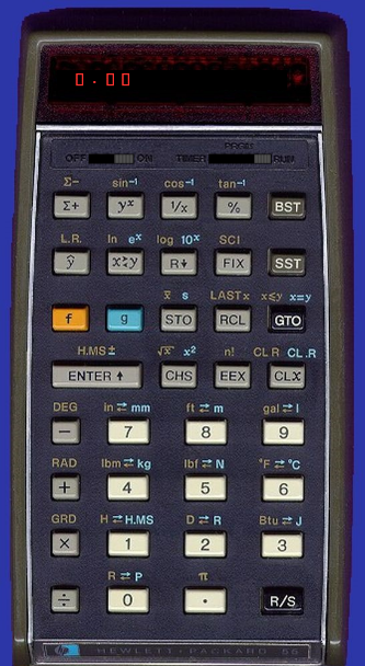
You can also run my HP-55 emulator in your browser to get a clickable keyboard.
Scancodes
These are what the calculator sees when you press a key.
| 6 | 4 | 3 | 2 | 0 | |
| 000 | ∑+ | y^x | 1/x | % | BST |
| 050 | ŷ | x<->y | Rv | FIX | SST |
| 010 | f | g | STO | RCL | GTO |
| 070 | ENTER | CHS | EEX | CLx | |
| 060 | – | 7 | 8 | 9 | |
| 020 | + | 4 | 5 | 6 | |
| 030 | * | 1 | 2 | 3 | |
| 040 | / | 0 | . | R/S | |
E.g. the scancode for ENTER is 076.
KeyCodes
These are what the calculator displays when you are in PRGM mode.
| 11=∑+ | 12=y^x | 13=1/x | 14=% |
| 21=ý | 22=x<->y | 23=Rv | 24=FIX |
| 31=f | 32=g | 33=STO | 34=RCL |
| 41=ENTER | 42=CHS | 43=EEX | 44=CLx |
| 51=- | 07=7 | 08=8 | 09=9 |
| 61=+ | 04=4 | 05=5 | 06=6 |
| 71=* | 01=1 | 02=2 | 03=3 |
| 81=/ | 00=0 | 83=. | 84=R/S |
For [GTO] [n] [m], this is displayed as “-nm”. E.g. GTO 0 6 displays as “-06”.
PrgmCodes
These are the values stored internally, in program memory.
| 11=∑+ | 12=y^x | 13=1/x | 14=% |
| 21=ý | 22=x<->y | 23=Rv | 24=FIX |
| 31=f | 32=g | 33=STO | 34=RCL |
| 41=ENTER | 42=CHS | 43=EEX | 44=CLx |
| 48=- | 07=7 | 08=8 | 09=9 |
| 38=+ | 04=4 | 05=5 | 06=6 |
| 28=* | 01=1 | 02=2 | 03=3 |
| 18=/ | 00=0 | 16=. | 15=R/S |
Others: 50 – 99 = GTO 00 – GTO 49 (merged keystrokes).
There are a lot of unused codes (eg 17, 19, 20, 25, 26, …).
You can also store f or g prefixes before keys that don’t have f or g functions (eg g FIX and f /).
Memories
The HP-55 has 20 data storage registers: memory .0 – .9 and 0 – 9 (eg STO . 1, RCL 2).
It also has 7 registers as program memory (7 x 7 steps in each = 49 program steps).
It has 3 more internal-use memories for a total of 30. These are:
| ram[0-9] | Memories .0 to .9 |
| ram[10-19] | Memories 0 to 9 |
| ram[20] | Internal – LastX |
| ram[21] | Internal – used |
| ram[22] | Internal – ??? |
| ram[23-29] | Program memory |
You can STO or RCL 0 to 9 and . 0 to . 9; but you can only STO +,-,*,/ 0 to 9 not the dot versions.
S Flags
The s flags are single bit settings that the calculator microcode uses to remember some things. You only see these when stepping through the microcode. These are:
| s0 | key_pressed. Set by the hardware. |
| s1 | dsp_prefix (FIX or SCI) (2) |
| s2 | mem_prefix (STO or RCL) (2) |
| s3 | PRGM (1) |
| s4 | g_prefix (2) |
| s5 | error |
| s6 | f_prefix (2) |
| s7 | auto_enter or, if s9 also, dot_pressed |
| s8 | (1) |
| s9 | digit_entry |
| s10 | if s9 also, eex_pressed |
| s11 | TIMER (1) |
The s flags show up on the microcode screen like “0..3……ab”. In this example: s0, s3, s10 and s11 are set (=1). The others are clear (=0).
(1) s3 and s11 are “tied” to hardware through the TIMER-PRGM-RUN switch.
If the switch is in the PRGM position, s3 will always be set and clearing it has no effect.
If the switch is in the TIMER position, s11 will always be set and clearing it has no effect.
In the RUN position, combinations of s3, s8 and s11 are used to allow the microcode to return across ROMs. The combinations of s3,s8,s11 are: 00x rom 1, 01x rom 4, 100 rom 2, 101 rom 5, 110 rom 0, 111 rom 3. Doing a goto 00711 “subout” will result in a switch to the specified ROM and then a “return” instruction being run.
(2) These are cleared as a set, see 01761 which “clears all prefixes”, probably after a function.
(3) Some flags get reused. e.g. in TIMER mode: s6 is timer_stopped and s8 is used for key debounce (s8 is set a short time after a key was pressed); in RUN mode, s5 is used during SIN/TAN to select which result is produced.
M Register
M is a 14 nibble (14 x 4 bit) register inside the calculator CPU. It can store 14 binary-coded-decimal numbers like the rest of the calculator and memory registers. However, it is used for more flags, and for settings that require more than one bit. The settings stored here are:
| M[13] | 0, 2=GTO, 1=GTO n, 0=GTO n n (done) |
| M[12] | 0, 1=Running, 0=Stopped |
| M[11] | 1, Set to 1 in the wait loop. Why? |
| M[10] | 1 |
| M[9] | 0 |
| M[8] | 0, 0=FIX, 1=SCI (cur display mode) |
| M[7] | 2, 0-9 for FIX/SCI 0-9 (cur display precision) |
| M[6] | 0, 0=DEG, 1=RAD, 9=GRD |
| M[5] | 0 |
| M[4,3] | 00, Program counter (PC) 00-49 |
| M[2] | 0, if s2: 0=STO 1=RCL 2=STO. 3=RCL. 4=STO+ 5=STO- 6=STO* 7=STO/ |
| M[1,0] | 00, used / temp |
The first value shown for each is the value after startup.
During the WaitLoop, M and C are swapped so you’ll see M values in the C register.
If s2 is set, we know that a memory STO or RCL has started and is not yet complete; but we don’t know which one. M[2] provides additional information on the keys pressed so far.
There isn’t an “s flag” for GTO pressed. Instead, it sets M[13] to 2 and counts down from there as it gets additional keys.
In the emulator M[13] is the leftmost digit and M[0] is the rightmost.
Microcode
The microcode can be seen in this HP-55 ROM listing. Key locations in the microcode are:
| Addr | Name | Notes |
| 04170 | WaitLoop | RUN loop waits for keypress or switch change |
| 04145 | KeyPressed | aka wat1 |
| 04146 | Debounce | wat2: a delay loop |
| 04162 | onScanGo | tkr: use the scancode jump table |
| 04660 | onPrgmGo | run: process a program code |
| 04230 | Display | dis99: display result |
| 04167 | ErrLoop1 | toggle display on/off if s5=1 |
| 05543 | TimerWait | TIMER loop waits for keypress or switch change |
| 05573 | TimerRun | TIMER loop updates 100ths of seconds |
| 00711 | subout | far return across ROMs using s3,s8,s11 flags |
ROM Addresses
The microcode includes instructions to select roms 0-7. It also includes a “delayed select group” instruction which selects the “0th” set of 8 roms or the “1th” set. There are a total of 12 roms in the HP-55. By convention, they are numbered 0-7 and 10-13 (i.e. in octal).
| From | To | Chip |
| 00000 | 00377 | rom 0 |
| 00400 | 00777 | rom 1 |
| 01000 | 01377 | rom 2 |
| 01400 | 01777 | rom 3 |
| 02000 | 02377 | rom 4 |
| 02400 | 02777 | rom 5 |
| 03000 | 03377 | rom 6 |
| 03400 | 03777 | rom 7 |
| 04000 | 04377 | rom 10 |
| 04400 | 04777 | rom 11 |
| 05000 | 05377 | rom 12 |
| 05400 | 05777 | rom 13 |


