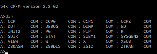
CP/M 2.2 Gen 2 is a standard CP/M 2.2 installed in a non-standard way on non-standard hardware. It has some benefits over the usual arrangement; yet it looks quite normal:
What’s different?
Firstly, it loads the CCP as a normal file rather than from the system area of the disk. This means you can change CCPs by simply copying another one over the top. Here’s some examples:
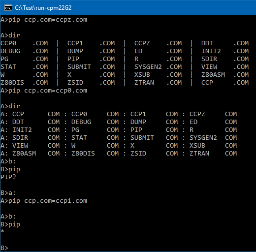
Here you can see PIP being used to swap to CCPZ, the original CCP (CCP0) and the patched CCP (CCP1).
CCPZ has a different look to its DIR command. CCP0 doesn’t find PIP when you are on Drive B:. CCP1 includes looking on the A: drive for programs; so it does find PIP.
You could switch to any other CCP replacement just as easily. You don’t have to splice it into the system tracks of your boot disk. (It does have to be on your A: disk though).
The idea isn’t new. It was around with CDOS 1.07. Cromemco moved their CCP into a file called CONPROC.COM and it worked pretty much the same way as this. Their reason for doing it this way was probably to make room in the system tracks for a larger BIOS as the Cromemco hardware isn’t the easiest stuff to control and there isn’t a lot of space for the BIOS to do so. A standard (8″ SSSD) CP/M 2.2 system has 2 reserved (system) tracks of 26 x 128 bytes each. This gives enough space for 1A00H bytes of Operating System. The CCP takes up 800H, BDOS 0E00H and BIOS has the remaining 380H (there’s an 80H boot sector at the front). 380H should be a reasonable amount of space but CP/M 2.2 contains tables for the Disk Parameter Headers (DPHs), Disk Parameter Blocks (DPBs) and skew (or translate) tables for each of the disks. You run out of room fairly quickly.
For my cpm22 Gen 2 system, I’d already decided to use an 8″ DSDD boot disk and that gives 64 x 128 bytes (2000H) on a single track for the Operating System. I wasn’t running out of space in the system area. I did however, like the convenience of being able to plug in a CCP replacement by simply copying a new one on.
A Smarter BIOS
Given I didn’t need the extra space and I now had some, I decided to add some “smarts” to the BIOS. As a result, it can recognise a number of common disk formats and adapt to them. The recognised types are 8″ DSDD, 8″ SSSD and 5″ SSSD. If you want a large system use large disks. If you want to copy to more standard size disks use one of the SSSD formats. How? Just format a disk of that size in that drive (with INIT2.COM). The BIOS will notice the disk type and reconfigure to match. Here’s an example of what you can get:
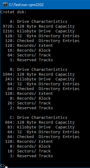
Drive A is 8″ DSDD (you can’t change that one). Drive B is 8″ SSSD. Drive C: is 5″ SSSD. You can add a drive D. You can change B or C by reformatting them or, if you already have a disk image, copying that into the host directory as driveb.dsk, drivec.dsk or drived.dsk. Reconfiguring happens on every warm boot.
Easier Hardware
If you look through the G2 BIOS, you’ll see the hardware has been optimised for CP/M. Even when you go to Double-density disks (which have 200H sectors), the floppy disk controller reads and writes in 128 byte records. When I did a double density BIOS for Cromemco hardware, I had to read in a full sector (200H), update a CP/M record (128 bytes) and then write out the whole sector again. It was messy, lengthy and inefficient. Having the controller work in CP/M’s native size made everything much simpler. Double-density sectors are still 200H long; but the controller happily reads or writes parts of them. The blocking and deblocking code that had to be in a CP/M 2.2 BIOS, and which got included in the CP/M 3 BDOS, all happens for me inside the controller. That’s really how they should have made floppy disk controllers and it’s what caused me to name the new hardware “G2” or “Gen2”.
CP/M never had “double-sided” built into it. As far as CP/M is concerned, drives have tracks and sectors. It never considered heads and those of us that have written BIOSes for DS disks (or multi-cylinder HDDs) have typically mapped the heads to more tracks. There’s quite a bit of code to swap between the different numbering schemes and you have to be careful that you store and use the same track types when you are translating between them. For Gen2, the computer side of the disk controller only thinks in tracks. This fits perfectly with how CP/M thinks of storage. There’s no translation required.
Here’s an extract of what is often the hardest parts of the BIOS:
SETTRK	LD 	A,B
	OUT	(FDCTRKH),A	;STORE THE TRACK NUMBER
	LD 	A,C
	OUT	(FDCTRKL),A	;STORE THE TRACK NUMBER
	RET
;
SETSEC:	LD	A,C
	OUT	(FDCSECT),A
	RET
;
SETDMA	LD 	A,B
	OUT	(FDCDMAH),A
	LD 	A,C
	OUT	(FDCDMAL),A
	RET
;
HOME:	SUB	A
	OUT	(FDCTRKH),A	;STORE THE TRACK NUMBER
	OUT	(FDCTRKL),A	;STORE THE TRACK NUMBER
	RET
;
READ	LD	A,1
	OUT	(FDCCMD),A
	IN	A,(FDCCMD)	; 0=ok, NZ=error
	RET
Bear in mind that the above works for all disk sizes, all sector sizes and single-sided / double-sided / other-sided disks; without change. Before this, I’d needed to set a bit to select the relevant head and another to specify single or double density. I’d also needed to read different size sectors depending on the bit. There was another bit to select 5″ or 8″ disks and often the bits were packaged up with other information so I’d need to remember and send the same bit multiple times (with the other information).
A Simpler Boot Loader
The standard booting process for CP/M is a bit complex. Firstly, a boot sector gets loaded, somehow, into memory and run. That then loads the rest of the operating system in and starts it up.
The main plus of the process is that you only have to get one sector into memory to get the whole OS up and running.
The main minus is that the sector is all on its own. It doesn’t have (yet) an operating system to do things for it. Everything it does has to fit in that one, typically 128 byte long, sector. That’s: error messages, stepping the drive motor to the right track, reading sectors in, changing formats (ie single to double density on disks which format track 0 as single density) and changing sector sizes too if density changes. If heads change and there are bit(s) to do that then you need to include code to change those bit(s).
The second minus is that you have to do it all again. The boot sector is, almost always, one-off code. It is never used after it has done its job. Despite the boot sector having the necessary code to read sectors from disk, the BIOS includes the same code. It tends to be a little different because CP/M puts parameters in less optimum spots and size constraints require optimizing the boot sector. It gets even worse with CPM3 as that has a boot sector that loads a loader that loads the operating system. There’s code to read a sector in the boot sector, in the Loader BIOS and in the CPM3 BIOS.
The third minus is optimising a boot sector to fit in 128 bytes usually means making it work for a single disk type. When space is limited, it is hard to include features that aren’t needed for this disk type so, typically, the boot sector is different for each disk type. For this reason, copying an OS from one disk type to another, usually results in an unbootable disk – the boot sector doesn’t work.
For the Gen2 system, I took the opposite approach. Instead of loading a sector into memory; I load all of the system tracks into memory. If I’ve got to get a sector in, somehow; I may as well get the others in too.
The Gen2 controller includes a “read track” command. That reads from the current sector to the end of the track. It’s a single command so it’s easy to do. It also updates the DMA address in the controller and the track and sector number too. That makes it easy to read the next track into memory after the last one. Again, it’s one command. The nice thing about “read track” is that it works for any number of sectors per track and any density or sector size. It works for mixed density disks (SD track 0, DD afterwards). It works for any disk size. Given that the controller doesn’t deal with heads (side0/side1) on the computer side of the interface, it also works for SS or DS disks. The following boot works for any disk:
	SUB	A
	; boot from drv A
	OUT	(DISK),A
	; start at track 0
	OUT	(TKHI),A
	OUT	(TKLO),A
	; start with sector 1 of track 0
	LD	A,1
	OUT	(SEC),A
	; load to 0100H
	LD	HL,0100H	; DMA to loadaddr
	LD	A,H		; set DMA
	OUT	(DMAHI),A
	LD	A,L
	OUT	(DMALO),A
	; load
	LD	A,3		; read track (0)
	OUT	(CMD),A
	LD	A,3		; read track (1)
	OUT	(CMD),A
	LD	A,3		; read track (2)
	OUT	(CMD),A
	; run
	JP	0100H
The “boot sector” at the start of the OS becomes a simple LDIR instruction to put the OS into high memory and then a JP instruction to the Cold Boot jump address at the start of the BIOS. You can easily fit “two” instructions in a 128 byte sector. (It’s a little more than “two” because you have to set up registers for the LDIR; but there’s still plenty of space left.)
I load three tracks, always, because the worst case (5″SSSD) requires three tracks. The LDIR bit only moves the OS bytes. It knows how long that is and it is constant for an OS, regardless of how many system tracks were needed and what size those tracks were.
You end up with a single boot program that will load any OS from any disk. Nice.
Given that I load the OS at 100H and up, you can also test an OS by running it from any active OS, just like a normal program. (Save it as a .COM file and run it. The “boot sector” at the start relocates it to the correct memory address and then JPs into it to start the new OS.)
Loading the OS to 100H doesn’t interfere with other programs that run there. Nor does it prevent you from SAVEing memory images of programs. This is because the OS only loads to 100H at COLD boot time – before any programs have been loaded.
A better X.COM
X.COM is mainly for eXiting the CP/M computer, but is used to tell you a little about the host environment too. Given that I now have different hardware in my windows builds of z80sim (z80sim.exe and z80sim2.exe), the “X H” command now tells you about the emulated hardware too. It looks like:
C>x h
Host software  : z80sim 1.35 / Win Build 0.14
Host emulation : GEN2 hardware
Host directory : C:\Test\run-cpm22G2

C>
This is part of the CP/M topic.
You can download run-cpm22G2 from cpm/z80sim/run-cpm22G2.zip.
The source code for:
– z80sim2.exe with the Gen2 hardware is in cpm/z80sim/z80sim-0.14.zip
– the BIOS is in cpm/misc/bios/bios(sim,cpm22G2).z80
– the BOOT is in cpm/misc/boot/boot-simG2.z80.
You can read more about running an entire CP/M system with one-click in run-cpm.


